

DISCLAIMER:
We are not responsible for anything wrong (including electric shocks, malfunctions, fires, accidents involving a soldering iron) that might happen during the assembly of the kit. Everything you do while assembling the kit is at your own risks.
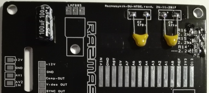
SMD Resistors:
-1x 390r (R9) labelled 3900
-1x 750r (R8) labelled 7500
-1x 470r (R7) labelled 4700
-4x 2,2k (R11- R14- R15 -R16) labelled 222
-3x 47K (R1- R2- R3) labelled 4702
-2x 220K (R4-R6) labelled 2203
Capacitors:
-3x 470nF labelled 474
-1x 100uF
Diodes:
-2x 1N4007 (D1- D2)
-1x 1N4148 (D3)
Led:
-1x 3mm red
-iC:
-1x Arduino Nano
-1x LM7805 (TO220 package)
-1x TL074 CDR (SMD package)
Trimmer:
-2x 50K Lin
Switchs:
-1x Push Button Latching Switch ON/OFF 8x8mm + 1x White cap
-2x Push Button Momentary Switch ON/OFF 8x8mm + 3x Blacks caps
Pin headers:
-2x 5 pin 2,54mm (10 pins Eurorack connector)
-2x 15 Pin 2.54mm Single Row Right Angle Female Pin Header
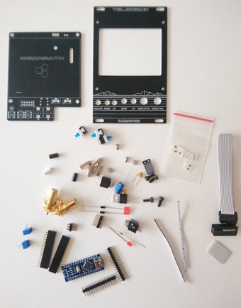
Miscelaneous:
-1x Black PCB + 1X FR-4 Panel
-4x 12mm Hex spacer M3
-8x Screw M3x 8mm
-1x Power Ribbon cable 16p to 10p
-2x Mono Jack 3,5
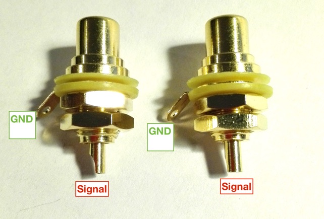
-2x RCA Phono connectors
-Rubber tape X3
3,5 LCD Display:
Check this FAQ before ordering an LCD screen for your kit:
Assembly instructions (Telewizor FR-4 edition, DU-NTSC, Vector):
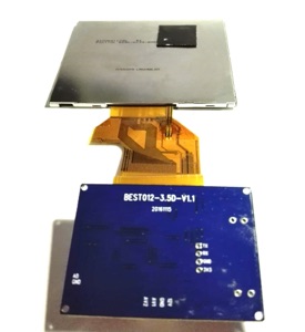
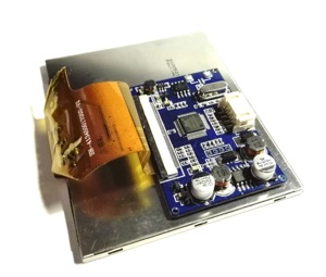
Step 1: Check your display!!!!
You will facilitate the entire build and avoid stress and disappointment by now testing the display as follows:
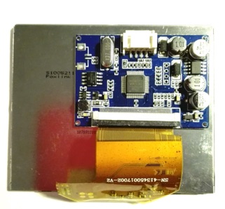
Clip carefully the Driver flat ribbon on the Display port (number of pin and drivers board may vary from Suppliers). Powered the display with +9 or +12V (You can use a 9V battery, but basically the display will turn off after 7/10 minutes of use and totally drain off the battery)
-Connect a composite signal on AV1 port (Any composite signal from DVD player, video generator, video games etc…)
-Connect now another composite signal on AV2: The display will automatically switch and display the signal applied on AV2!!! This is a really important function for Telewizor. If this does not work, Telewizor will only display the internal Video Generator and no external signal.
If you have an issue, try to connect a composite signal on AV2 first, then on AV1 and check if switched.

Ready for populating the main board?
Step 1:
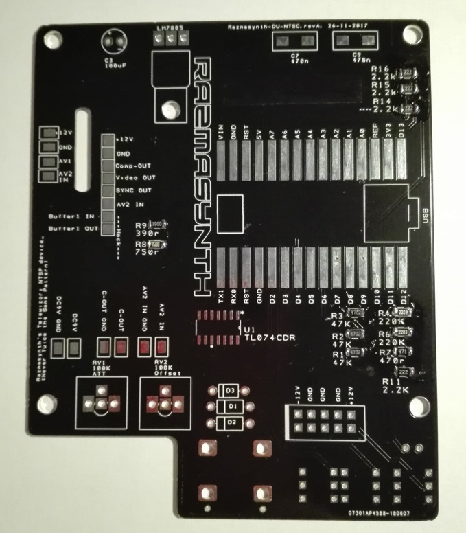
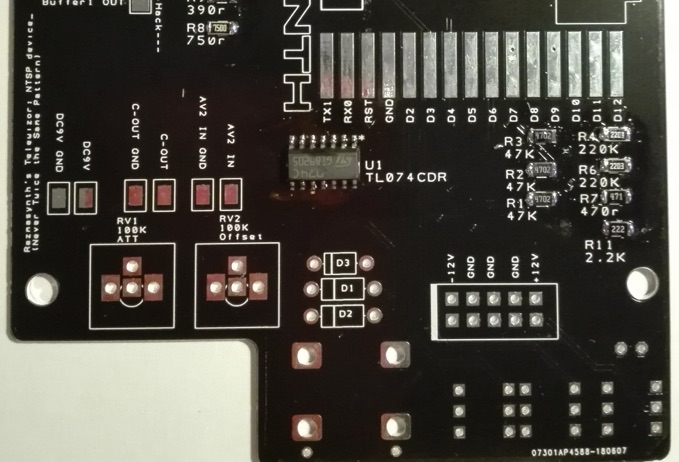
The SMD resistors:
Only one rule for soldering CMS: Apply solder on the first pad only, solder the first leg of the component, and then directly solder the rest. Using solder flux for any SMD part of Telewizor (Resistors, Op-amp, right angle female pin headers) prevent the troubles as solder bridge and insufficient solder.
The resistors have a value code, pay attention to not mix 470r and 47K or 2,2K and 220K.:
-1x 390r (R9) labelled 3900
-1x 750r (R8) labelled 7500
-1x 470r (R7) labelled 4700 or 471
-4x 2,2k (R11- R14- R15 -R16) labelled 222
-3x 47K (R1- R2- R3) labelled 4702
-2x 220K (R4-R6) labelled 2203 224
Step 2:
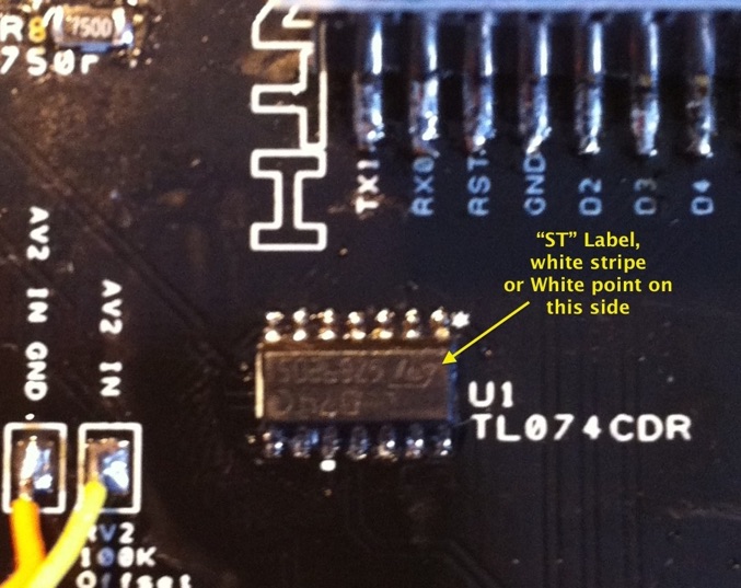
The SMD Op-Amp:
Apply solder on the first pad only, solder the first leg of the component, and then directly solder the 7 others. Use Flux 😉 Pay attention to his orientation since it’s a polarized component.
Step 3:
The capacitors:
-The 2x 470nF labelled 474 are not polarized
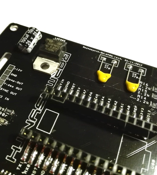
-Then the trough holes 100uF. PLEASE BEWARE THE POLARIZATION (See pic below for correct implementation)
Step 4:
The Diodes:
Solder the two polarized diodes 1N4007 D1 and D2 and D3, pay attention to their orientation since they’re polarized components.
Step 5:
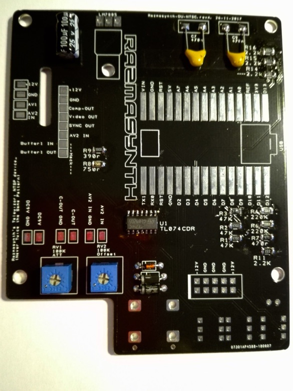
Trimmers:
Solder first the trimmer’s midle pad, adjust the trim and solder quickly the two others. The PCB is labelled «100K» because you can use 50 to 100K lin trimmers, but 50K offered a finest tune.
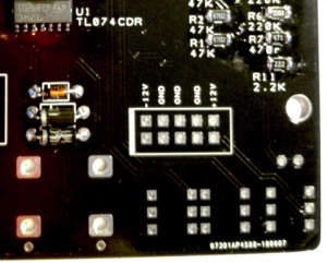
Step 6:
The Eurorack Power Bus connector:
When the pin headers are soldered, immediately verify the solder quality & if you didn’t forget any pin.
Don’t power your board now (even to test the CV) because the TL072 will overheat if the device is powered before the 3.5 jack from CV is not soldered to the board.
The Arduino board:
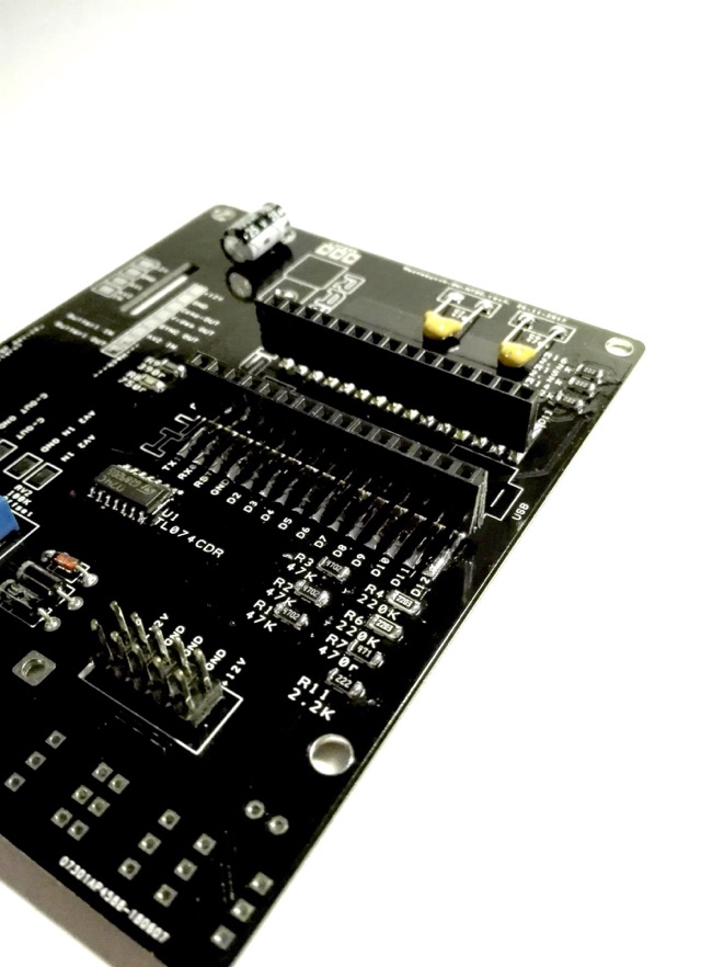
Step 7 :
Solder the 2 x 15 pin header on the board, immediately verify the solder quality & if you didn’t forget any pin. Take care to the solder side!!!!!
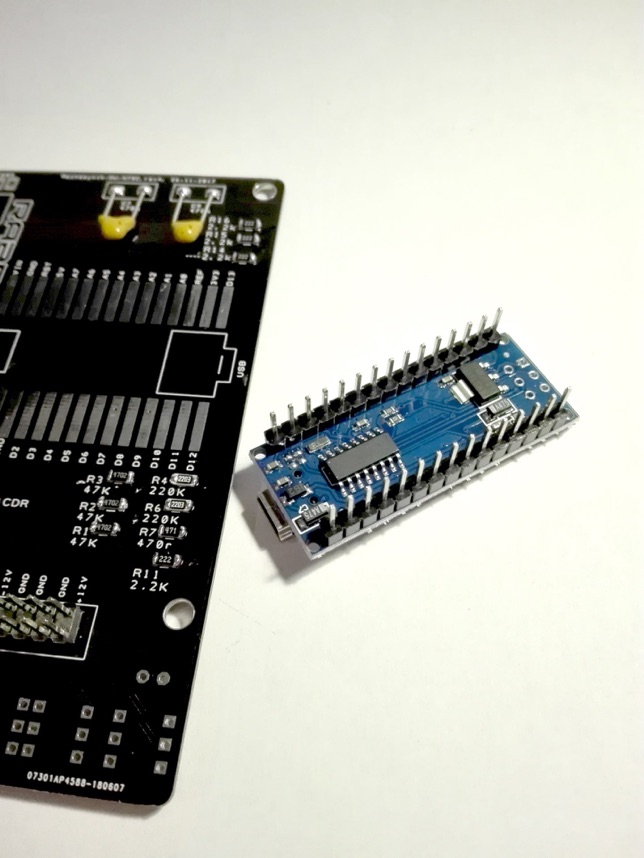
Now plug the Arduino Nano board on the female pin headers as is (right angles pins turned to the external sides)
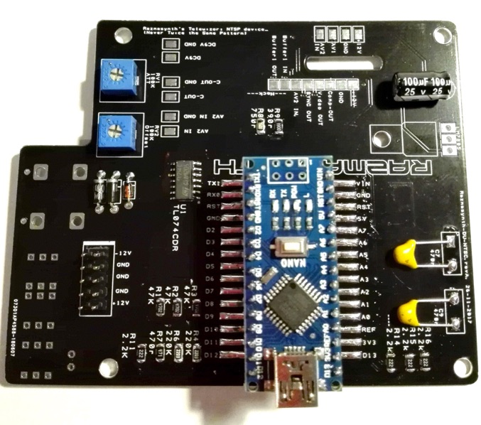
And now, the most difficult part of the build, soldering the Arduino Nano female socket to the board:
-Apply flux on all the pads. Then solder the first pad only, solder the first leg of the right angle pin header, center the Uno and apply solder on both pads. Remove the Uno and check every solder.
Step 8:
The Led:
Solder the 3mm LED. Pay attention to the orientation since they’re polarized components. Flat side on the footprint= Short Leg.
Step 9:
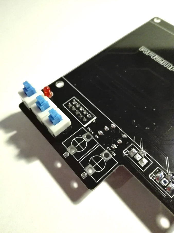
The Push Button Switchs:
There are two categories: 1 Latching (Blue and white package produce a latching sounds «Click, click») and 2x Momentary (Black and white package or blue and white).
Mount these 2 switches. Ensure they snap-in fully into the holes and are flat against the PCB. Solder the middle side pads, and check if they are nicely aligned. Solder the other middle side pads and re-check the alignment. Finish soldering the 4 other pads
Work quickly! No more than 3 seconds per joint! If you must resolder a joint, allow Switchs to cool for 20 seconds.
Step 10:
The 5V regulator:
Take care to his orientation, it’s a polarized component.
Step 11:
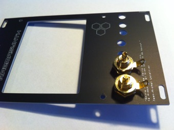
Connectors:
Start with the two RCA connector. Screw it on the panel. No worry if you can’t screw the RCA connector with the small round nuts ( I also have large fingers and I let them aside).

Step 12:
The LCD Screen:
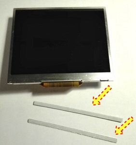
Now, glue the small square tape on the back of the screen. This will be used for bonding the Driver’s PCB on the Screen’s back.
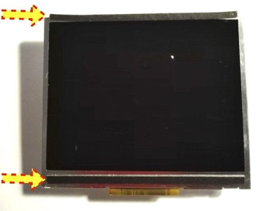
Now remove the adhesive transparent sheet from the Screen. Use two pieces of double-sided tape and glue them up and down from the screen. (Usually a thin for the upper part and a larger for the lower part).
Check on the other side if you are in front, then glue your screen to the back of the aluminium panel
or FR-4 black matte epoxy panel, depending if you build Vector or Telewizor FR-4. You can powered your LCD screen and send a video signal in order to help you to glue the LCD at the right place.


Now, remove the wired connectors, unpowered from your DC supply if you previously powered your LCD screen and cut approximately 10cm of wire, then removed the black tube.

Slip the wires trough the window.
Now solder 4 wires between the two boards on the corresponding pads. All the pads are labelled.
-Red: +12V
-Black: GND
-White: AV1
-Yellow: AV2
To solder without mistake the wire, solder them one by one. At first the 12V wire, double check!!! Second, the ground wire and double check the silkscreen etc…


Step 13:
Panel assembly:
Now put the 4 caps to the Push Buttons and assembly the 15mm Hex spacers on the panel as is, screwed to the back and connect the wire from LCD driver to the main board:

Put the 3,5mm jacks in place BUT don’t solder now this components!!!
Then assembly the couple PCB/Panel together:

Now the most difficult part: Weld the 3,5mm Jacks at the right height!
Several way:
1)You can screw the nut if you want, but if you choose this way you should add a small piece of component lug to the every Jack’s Legs, if not, they will be away from the board and it will not be possible to weld them properly and thus ensure good electrical conduction.
- 2)In place you can try this: Manually adjust the height of the first jack, then solder only one pad. Manually adjust the height of the second jack and solder only one pad. if you are satisfied, then finish the welds of the remaining pads. If not, you can ajust a bit by heating the solder pad. Don’t forget to solder theyre small ground pads!!!
- 3)After this practice you are ready to start the disassembly of an honorable Vectrex game system from 1982 and replace all his capacitors without taking 25000 volts by touching the THT! (Thannnnnnkk’s so much Razmasynth’s guys!!!!!!!)


and don’t forget the ground tip (Use a component Lug, the remaining of the Diode fit perfectly)

And now solder the wires between the Cinch connectors and the board on the corresponding pads. «Display IN» to «AV2 IN» , «Video Out» to «C-Out» (C-out as Composite Out). The pads labelled DC-9V are optionals, late Telewizor V2 and DU-NTSC and Vector doesn’t have a dedicated DC connector’s hole on the front panel (See desc. bellow)

Important: When assembly, check if any pads from main PCB don’t touch anything on the Driver’s PCB. If the 4 solder pads are touching some components from the driver board’s, put a a piece of rubber tape or plastic sheet to isolate the pads. (But with king sized 15mm hex spacers that can’t happens..)
Step 14:
Now you finished the build, it’s time to calibrating your device:
Connect your Arduino Nano to the board, USB closed from the board’s side.
Powered now Telewizor by your modular power bus, the white stripe on the Eurorack connector figure the -12V, respect the polarity, but no worry if you reverse the flat ribbon, all the Razmasynth modules are protected against reversed polarity.
Important note: The external DC 9V solder pads allows you to power Telewizor without modular, using a 9V AC adapter.
Using an external power adapter, Telewizor can only be used as a display, not as a Video Generator or Oscilloscope, because this functions requires a bipolar power supply from modular. So, for calibrating Telewizor, you must connect the power ribbon to the modular. Another warning, don’t power Telewizor by the «Power Bus» and the external «DC Pads» at the same time!!! (And don’t email me because you get a lot of funny little smell

Push the Power push button, the red Led will bright and after 4/5 seconds (depending the Display Driver) the Razmasynth logo will appear on the screen and display the first program!!! Congrats your device work, it’s time now to calibrate your Vector!
Telewizor is designed to display a bipolar CV from +5V to -5V.
Select the OScilloscope sub-program with the menu button.
The «A» button change the sampling rate and allow you to display Audio signals from low frequency
The «FX» button change the Display Zoom from 1X to 4X (Not on DU-NTSC)
Now, the easiest way to calibrated your device is using a +/-5V Audio signal from VCO or LFO patched on the Telewizor CV IN.
On the Telewizor back, turn the «Offset» trimmer to height of your signal. Turn the «Att» trimmer (for Attenuverter) to increase or decrease you signal size. The perfect match is obtained when your signal is entirelly displayed, without flatted edges.
Note: The oscilloscope program from DU NTSC and Vector don’t display a frame around the trace.

You can double check your calibration with the Captain Blood Baby: The Baby can get a bit outside the screen, it’s not problem, but if it’s too much, the pattern will freeze or skip to another sub program: Your signal is to big for the uC and might be reduced (Oki oki, if the baby doesn’t move even with +5V/-5V from LFO that mean it’s too reduced…)

Step 15:
Hack Me!!!!!
Now your Telewizor is ready, but you probably want to hack your device, no?
-Telewizor’s analog section contain 1 Free Buffer, pre-wired. He’s labelled «Buffer 1 IN» and «Buffer 1 Out» on the board. Just connect In and Out. This buffer used 1 cells of the TL074. It’s a little bit slow to drive video signal, but perfect if you want to add some CV features to your devices.
Nobody thinks to turn Telewizor into 8 bits video game console?
Or replace the TL O74 by a faster Op-Amp and buffer the the composite signal form the Arduino (The TL074 is bipolar supplied (+/-12V), check the schematic for pinout)
-Hack the code!!!!
The entire code is based to the TV out library.
It’s a really exciting library. And we really had fun writing these code segments. I would particularly like to thank my friend Kévin Tkac for all the time he spent writing the basis of the Razmasynth OS in 2016.
You can find the last revision of the code here, the TV Out libray and the TV Font. We used the old Arduino IDE 1.0.6 and Arduino Nano. This Chinese Nano are currently using CH341G serial/usb chip. If you’re unable to upload a new code, just upload the driver’s chip from Here
If you cook you’re own Telewizor or DU-NTSC code, feel free to send me, I will be really happy to share it on this site!!!!!
This is the latest software revision: LINK
And TVOUT library:
And drag and drop the content of TVoutVE-RAZ file to your Arduino libraries folder (Users/Name/Documents/Arduino/Libraries on Windows and Mac. It’s an enhanced TVout library based to Nootropic work. (Use Arduino 1.0.5 if you had a problem to compile)
Knowing Bugs, Troubleshooting & Debug:
At the end of your build, if you get a black screen without any pattern and the video output is unable to send a signal to another display, follow this steps to debug your device:
-Check every solders, especially the ones from resistors 750r and 390r, they mix the video and sync signal as composite and send to the display driver board.
-Check the calibration procedure of the two trimers.
-Check the solders of your 3.5mm jack, especially the Gate Input. Did they connected to the ground via a small piece of wire as described above?
-The only restriction is that the Telewizor V2 code does not handle the Gate entry. So, if you have images on the Vector’s screen with the V2 code, then you have a problem with the Gate input (diode soldered in the wrong way, poorly soldered or broken jack). You can find this code on the Telewizor V2 building plan.
-If the screen is able to display a Video Composite signal applied to the external Input, but not the pattern of the module, you may have a problem closed to the Arduino ( Sockets? ) or the welds of the components cms.
-If the display is unable to display a composite signal applied to the external input, but the module’s pattern is good, you have wired the input AV1 and AV2 wires upside down, so reverse the white and yellow wires. Note that it is common for wire colors to be reversed by Chinese manufacturers. Sometimes AV1 is white, sometimes yellow.